Upcoming Events:
- Check out our new Google Calendar for committee meeting times!
Region V - End of Semester Update - Interesting Tidbits
There are a couple of things that I didn’t include in the other blog post. Below are a couple of tips and tricks and bodges we did to get things to work.
Good Planning.
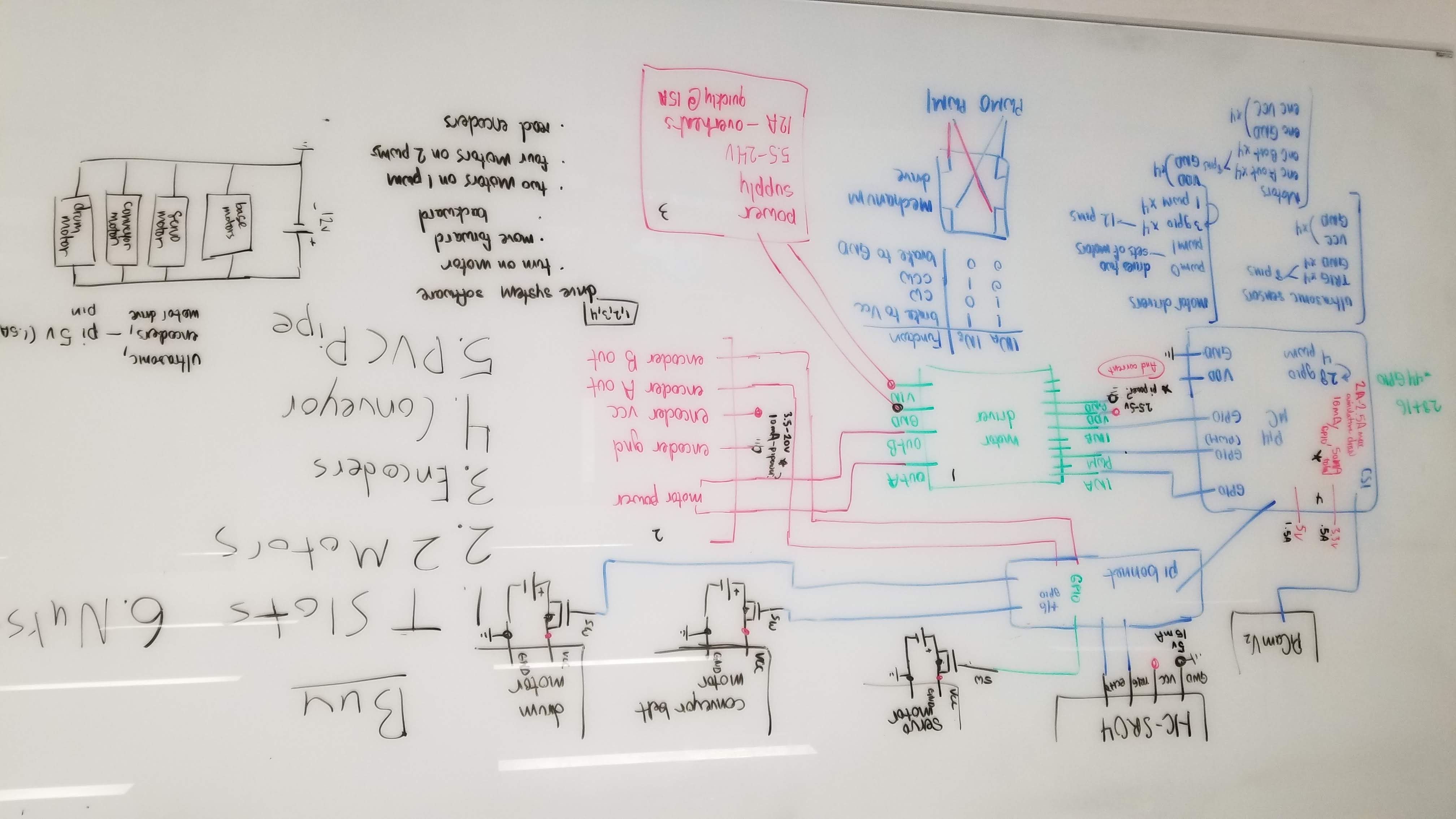 This first picture is the full circuit diagram of the robot, way at the beginning of the semester when I took over Electrical Lead. The mechanical team basically trapped me in a room and told me to figure out everything we needed before I could leave.
You can see that we have a fairly complicated system here, with ultrasonic (HC-SR04) sensors and the picamera detecting where we are, and motor drivers, motors, and servos actuating us. The hardest part was probably choosing how to allocate pins (we didn’t nearly have enough, which meant that we needed to buy a GPIO bonnet that extended off the I2C pins to accomodate all the parts) and how power distribution would work.
I spent a lot of time figuring out whether most of the components could be placed on the RPI 3.3V and 5V rails rather than the actual power supply. There are strict limits on how much current everything can drawn from the various parts of the PI like the power rails and the GPIO pins.
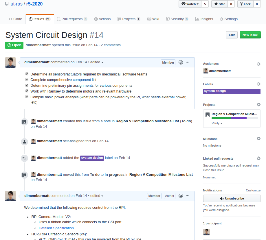
This second picture is one of many issues I populated in the first few weeks of this time consuming project. Using Github’s project board and issue system is very helpful to organize the tasks that needs to be done, and keep a place for relevant discussions (slack runs out of space so quickly that I lose my messages to myself weekly!). For example, I put all of my documentation for component spec sheets on here, as well as relevant summaries on what I needed to focus on in the development of the hardware of the system.
Bad Power Practices
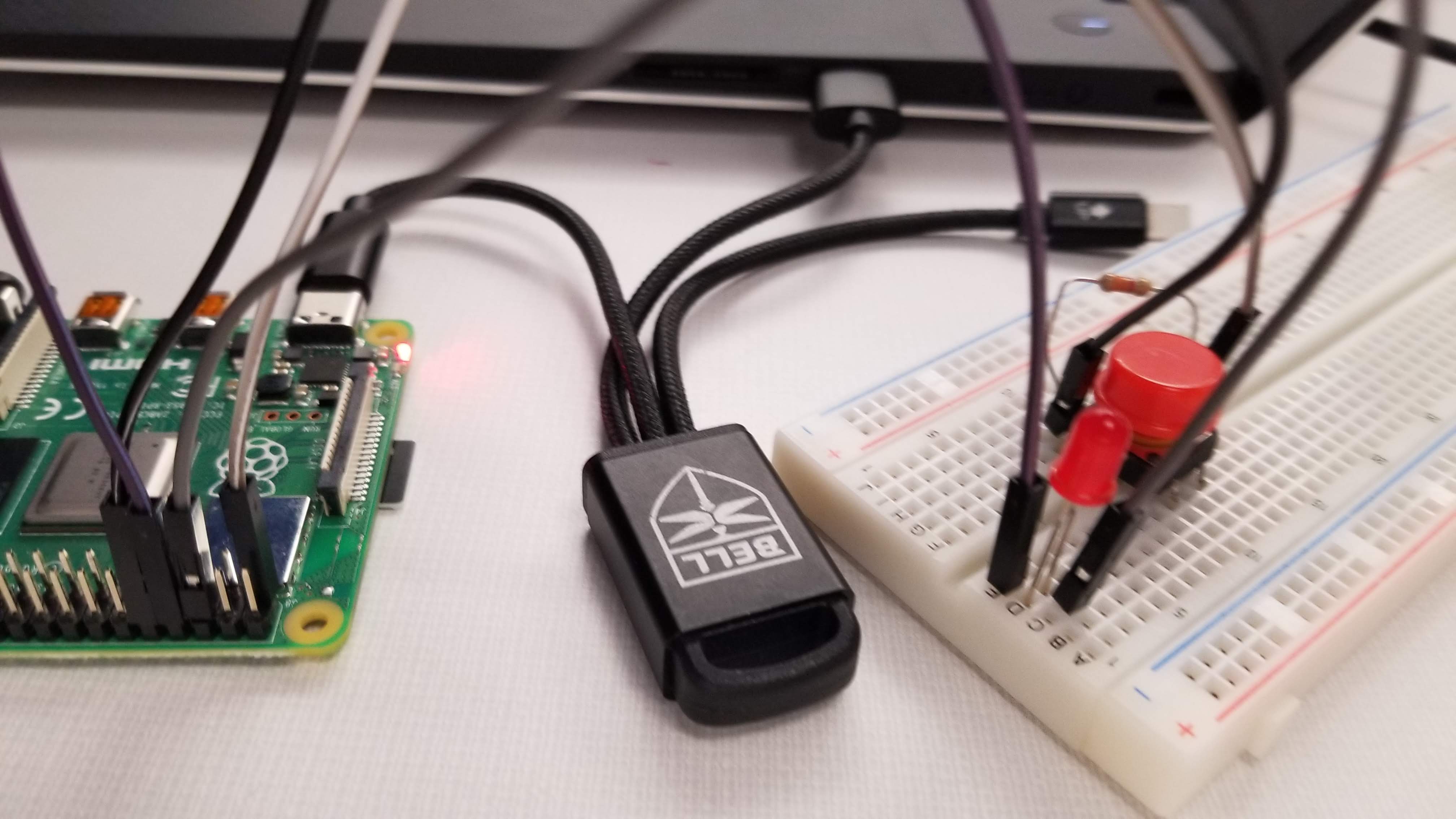 This picture is a bad idea. I was using some Bell Aerospace branded Chinese USB charger to power the RPI, and given that we frequently disconnect pins by accident, it’s easy to have a power surge and reboot the pi. Which is likely also why my XPS fails to recognize any USB device on the left side now…
Breadboarding
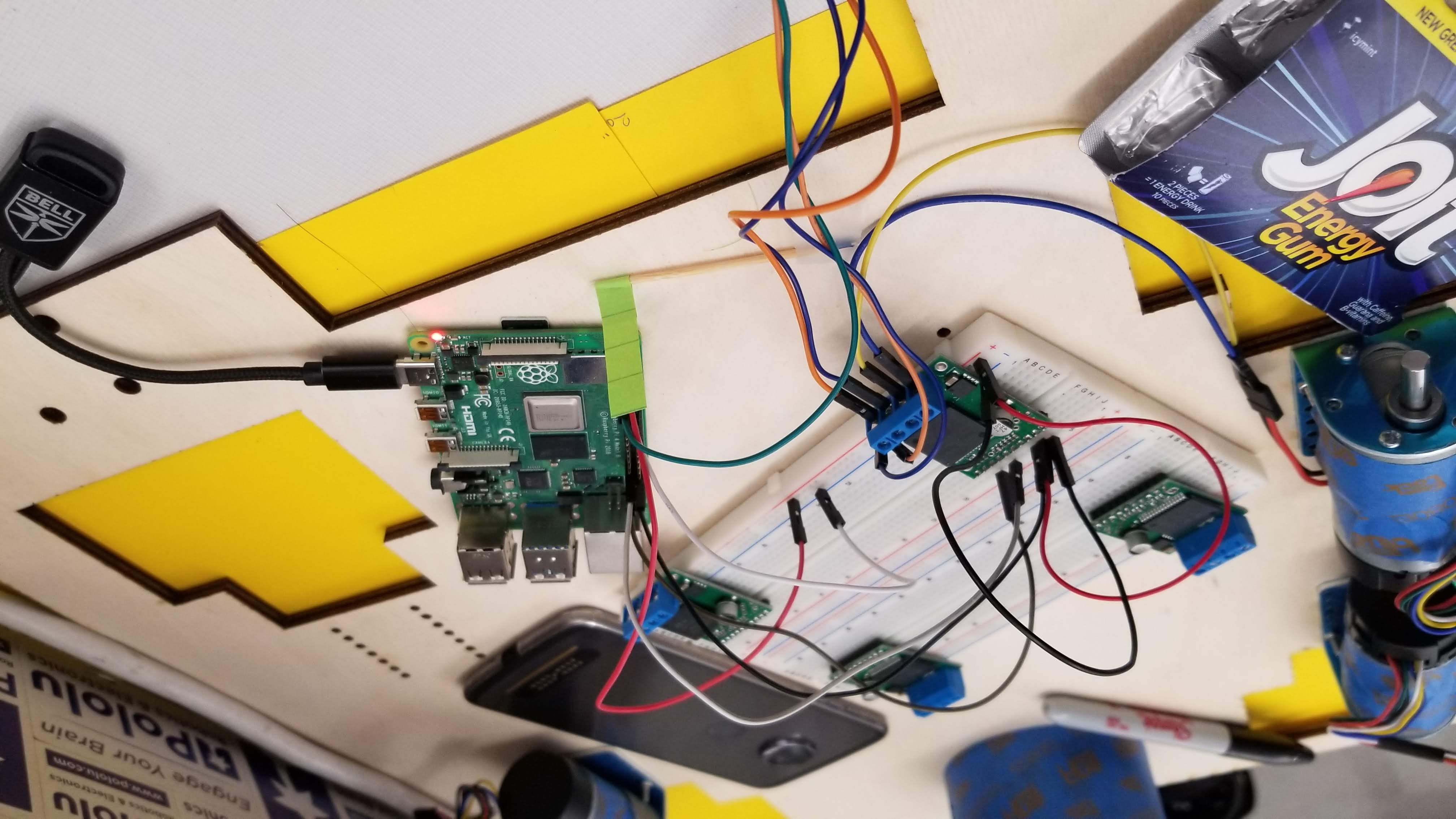 This picture was a subsystem test of the motor driver and motors. Prototyping on the breadboard was a good idea in part that it allowed me to position components across the wood base and get a good idea of where things should go for the PCB design. Measure twice and design once!
Validating somewhat accurately
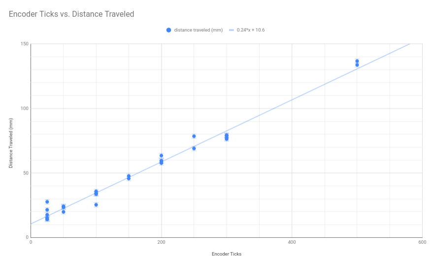
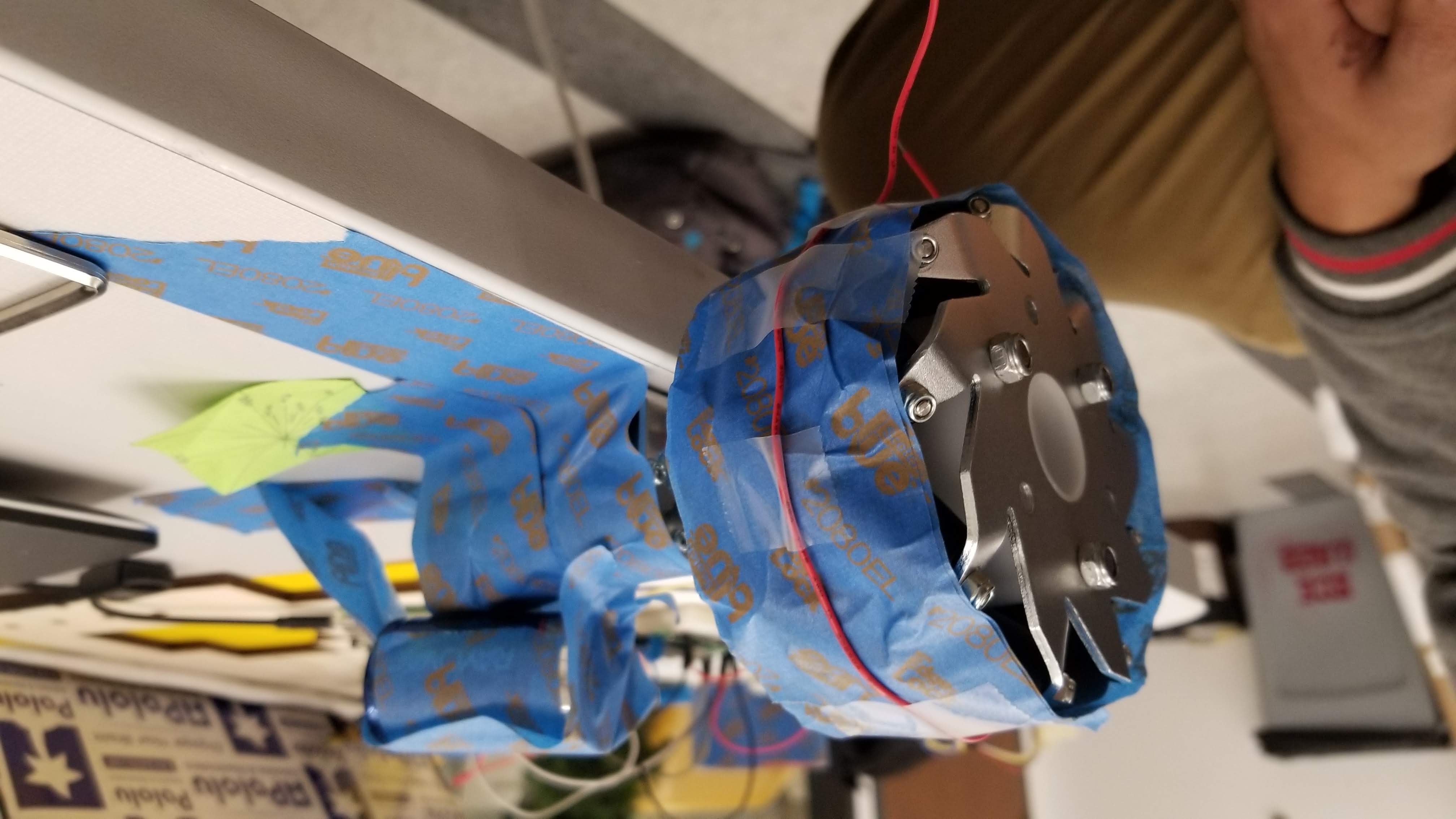 Finally here’s the real bodge of the day: we could not for the life of us figure out the precision of the encoder ticks to distance traveled. We tried several things:
-
A sticky note with angles on it and measuring the angle traveled after x ticks
-
A toothpick to act as the straight up reference
-
And this abomination, wire precariously wrapped around the wheel and measuring the wire traveled.
Ironically, the last option gave the most precise results.
Author: Matthew Yu (Electrical Lead for R5 and to soon be Electrical Lead for the Demobots Dancebots team)